FAQ

Power 277 General Frequently Asked Questions

Below you’ll find a list of general frequently asked questions. You can also browse our other sections regarding LED as well as Magnetic FAQ through the buttons above. If you have any additional questions that are not listed in any of the FAQ section we have on our site, please feel free to contact us at: 877-878-2348

Functionality Aspect FAQ ↓

  • A1. Notes on choosing a switching power supply?

    Answer:

    a. To increase the reliability of the S.P.S., we suggest users choose a unit that has a rating of 30% more power than actual need. For example, if the system needs a 100W source, we suggest that users choose a S.P.S. with 130W of output power or more. By doing this, you can effectively boost the reliability of the S.P.S. in your system.

    b. We also need to consider about ambient temperature of the S.P.S. and whether there is additional device for dissipating the heat. If the S.P.S. is working in a high temperature environment, we need to make some derating to the output power. The derating curve of “ambient temperature” versus “output power” can be found on our spec sheets.

    c. Choosing functions based on your application:

    • Protection function: Over Voltage Protection (OVP), Over Temperature Protection (OVP), Over Load Protection (OLP), and etc.
    • Application function: Signaling Function (Power Good, Power Fail), Remote Control, Remote Sensing, and etc.
    • Special function: Power Factor Correction (PFC), Uninterruptible Power Supply (UPS) function.

    d. Make sure that the model qualifies for the safety standards and EMC regulations you need.

  • A2. Can MEAN WELL’s power supply be used in the range of 45Hz ~ 440Hz? If YES, what will happen?
    Panel 2. Lorem ipsum dolor sit amet, consectetur adipisicing elit, sed do eiusmod tempor incididunt ut labore et dolore magna aliqua. Ut enim ad minim Answer:

    MEAN WELL’s power supply can be used within this frequency range. But if the frequency is too low, the efficiency will also be lower. For example, when a SP-200-24 is operated under 230VAC and rated load, if the frequency of AC input is 60 Hz, the efficiency is around 84%; however, if the frequency of AC input reduces to 50 Hz, the efficiency will be around 83.8%. If the frequency is too high, the power factor of the S.P.S. with PFC (power factor correction) function will reduce and this also will cause higher leakage current. For example, when a SP-200-24 is operated under 230VAC and rated load, if the frequency of AC input is 60 Hz, the power factor is 0.93 and the leakage current is around 0.7mA; however, if the frequency of AC input increase to 440 Hz, the power factor will decrease to 0.75 and the leakage current will rise to around 4.3mA.

  • A3. When testing a dual output power supply, the +5V channel is correct, but the +12V channel is over the specification. What is going on?

    Answer:

    There are some minimum-load requirements on MEAN WELL’s multi-output power supplies, please refer to the specification first before connecting the load. When the load condition is 5V/4A, 12V/0A, the output voltage of the 12V channel will be around 12.8V that is over the ?% of voltage deviation (12.72V) specified in the spec. sheet. If we add in the minimum load 0.2A to the 12V channel, the 12V channel will reduce to around 12.3V which is within the specification.

  • A4. Why did the power supply shut down during operation, but after turning it off, I can restart the power supply again?

    Answer:

    In general there are two circumstances that will cause the power supply to shut down. The first one is the activation of the over-load-protection (OLP). To deal with this situation, we suggest increasing the rating of the output power or modifying the OLP point. The second one is the activation of over-temperature protection (OTP) when the internal temperature reaches the pre-set value. All of these conditions will let the S.P.S. enter protection mode and shut down. After these conditions are removed, the S.P.S. will be back to normal.

  • A5. Why is the fan not running after turning on certain models?

    Answer:

    Some models control the fan based on internal temperature to extend its life time. For example, the Fan ON temperature for the S-240 series is ? 40C (RT1). If the internal temperature does not reach the preset value, the fan will remain still until receiving the start up signal.

  • A6. What is “Inrush Current”? What will we notice?

    Answer:

    At input side, there will be (1/2 ~1 cycle, ex. 1/120 ~ 1/60 seconds for 60 Hz AC source) large pulse current (20~60A based on the design of S.P.S.) at the moment of power on and then back to normal rating. This “Inrush Current” will appear every time you turn on the power. Although it will not damage the power supply, we suggest not turning the power supply ON/OFF very quickly within a short time. Besides, if there are several power supplies turning on at the same time, the dispatching system of AC source may shut off and go into protection mode because of the huge inrush current. It is suggested that these power supplies start up one by one or use the remote control function of S.P.S. to turn them on/off.

  • A7. What is PFC?

    Answer:

    PFC stands for Power Factor Correction. The purpose of PFC is to improve the ratio of apparent power and real power. The power factor is only 0.4~0.6 in non-PFC models. In PFC models, the power factor can reach above 0.95. The calculation formulas are as below:

    Apparent Power = Input Voltage x Input Current (VA)

    Real Power = Input Voltage x Input Current x Power Factor (W)

    From the environment friendly point, the electric power plant needs to generate a power which is higher than apparent power in order to steadily provide electricity to the market. The real usage of electricity should be defined by real power. Assuming the power factor is 0.5, the power plant needs to produce more than 2VA to satisfy 1W real power. On the contrary, if the power factor is 0.95, the power plant only needs to generate more than 1.06VA to provide 1W real power need. It will be more effective.

  • A8. What is the difference between -V and COM which are marked on the output side?

    Answer:

    COM (COMMON) means common ground. Please see below:

    Single output: Positive pole (+V), Negative pole (-V)

    Multiple output (Common ground): Positive pole (+V1, +V2,.), Negative pole (COM)

  • A9. In MEAN WELL’s catalog, we see AC and DC at input, what is it all about?

    Answer:

    Due to different circuit designs, MEAN WELL power supply’s input consists of three types as below:(?2VAC?VDC)

    • a. 85~264VAC;120~370VDC
    • b.176~264VAC;250~370VDC
    • c. 85~132VAC/176~264VAC by Switch; 250~370VDC

    In a and b inputs models, power supply can work properly no matter under AC or DC input. Some models need correct connection of input poles, positive pole connects to AC/L; negative pole connects to AC/N. Others may require opposite connection, positive pole to AC/N; negative pole to AC/L. If customers make a wrong connection, the power supply will not be broken. You can just reverse the input poles and power supply will still work.

    In c input models, please make sure that you switch the 115/230V input correctly. If the switch is on the 115V side and the real input is 230V, the power supply will be damaged.

  • A10. What is MTBF? Is it distinct from Life Cycle?

    Answer:

    MTBF and Life Cycle are both indicators of reliability. MEAN WELL uses MIL-HDBK-217F as the core of MTBF. An expected reliability is forecasted through accounting component’s number (exclude fans). The exact meaning of MTBF is after continuously using of power supply in a certain time, the probability of operating properly is 36.8%?e-1=0.368?. If power supply is continuously used at double the MTBF time, the probability of operating properly becomes 13.5%?e-2=0.135?.
    Life Cycle is found through using the temperature rise of electrolytic capacitor to estimate the approximate life of power supply. For example, SP-750-12 MTBF=769.3K hours; electrolytic capacitor C108 Life Cycle=202.2K hours (Ta=45?C).

  • A11. What is the fan control mechanism for SPS with cooling fan?

    Answer:

    Cooling fans have a relatively shorter lifetime (typical MTTF, Mean Time To Failure, of around 5000-10000 hours) as compared with other components of power supplies. As a result, changing operating method of cooling fans can extend the operation hours of the fans. The most common control methods are shown below:

    Temperature control: if the internal temperature of a power supply detected by a temperature sensor is over the set threshold, the fan will start working at full speed, whereas, if the internal temperature is less than the set threshold, the fan will stop working or at half speed. In addition, cooling fans in some power supplies are controlled by a linear control method whereby fan speed can be changed with different internal temperatures synchronously.

    Load control: if the loading of a power supply is over the set threshold, the fan will start working at fullspeed, whereas, if the loading is less than the set threshold, the fan will stop working or at half speed.

  • A12. What is power good and power fail signals and how can use it?

    Answer:

    Some power supplies provide a “Power Good” signal when they are turned on, and send out a “Power Fail” signal when they are turned off. This is usually used for monitoring and controlling purpose.

    Power Good: after the output of a power supply reaches 90% rated voltage, an TTL signal (about 5V) will be sent out within the next 10-500ms.

    Power Fail: before the output of a power supply is less than 90% rated voltage, the power-good signal will be turned off at least 1ms in advance.

    faq04

  • A13. What is minimum load requirement and how can I read it from the spec?

    Answer:

    MW’s multi- output power supplies, such as dual channels or more, will have minimum load requirements. It is highly suggested reading the spec before using them. For operating properly, each channel must deliver a minimum current or the output voltages will become unstable or be over the defined tolerance range. Minimum load requirement can be seen on spec’s “CURRENT RANGE” as the following table shows:
    CH1 requires a minimum current consumption of 2A, CH2 requires 0.5A, CH3 requires 0.2A and CH4 requires 0.2A.

    OUTPUT NUMBER CH1 CH2 CH3 CH4
    DC VOLTAGE 5V 12V -5V -12V
    RATED CURRENT 11A 4A 1A 1A
    CURRENT RANGE 2 ~ 12A 0.5 ~ 5A 0.2 ~ 1A 0.2 ~ 1A
  • A14. I have an TN-1500 inverter. Why the LED indication of AC IN is not lit after mains input has been applied?

    Answer:

    According to the mains voltage of different countries, the output of TN-1500 inverter 110VAC version can be altered to 100/110/115/120VAC. In the same way, TN-1500 inverter 220VAC version can be changed to 200/220/230/240VAC as well. When the inverter is set in UPS mode and the mains voltage fluctuates over ±15% of the set AC output voltage, the inverter will shift its power source from the city power to battery to remain the accuracy of the AC output Voltage. Meanwhile, the AC IN indicator on the front panel of the inverter will be turned off.


Application Aspect ↓

  • B1. How do we choose a power supply to charge a battery?

    Answer:

    MEAN WELL has ESC, SC, PA, PB series for battery charger purpose (120~360W). If these series does not meet customers’ demands and they like to choose a power supply as a charger, we advice to pick up one which over load protection (OLP) mode is constant current limiting. The models in this mode provide constant current even when the protection circuit is triggered.

    The second choice is fold-back current limiting or constant wattage model. In this model, when a battery is running low, the output current of the power supply will gently increase. The level of increase depends on battery’s capacity and degree of exhaustion.

    Hiccup or shut down model are not recommended because it will stop to generate current when OLP happens.

  • B2. If we need a 24V output power supply, but MEANWELL does not have this model, can we use two 12V power supplies connecting in series instead of one 24V power supply?

    Answer:

    YES, basically you can do this to get the right output voltage, but be careful that the rated output current of the series system should be the rating of the minimum one in these series connected power supplies. Furthermore, we like you to parallel a diode at the output of power supply to prevent possible damage of internal capacitors.

  • B3. If we need a 600W output, can we use two units of S-320 connected in parallel?

    Answer:

    No, you can not do this connection because S-320 is not equipped with the parallel function. When two power supplies are connected in parallel, the one with higher output voltage will share more loading and deliver more (even “all”) power to the load and cause these two power supplies to be unbalanced. We suggest using PSP-300 or PSP-500 because it is equipped with the current sharing function.

  • B4. Why can’t I turn on the power supply smoothly when the loads are motors, light bulbs or capacitive loads?

    Answer:

    If you connect the S.P.S. to motors, light bulbs, or high capacitive loads, you will have a high output surge current when you turn on the S.P.S. and this high surge current will cause failure of start up. We suggest using S.P.S. with constant current limiting protection to deal with these loads.

  • B5. The output ground (GND) and frame ground (FG) is the same point in my system, can MEAN WELL’s power supplies be used in such system?

    Answer:

    Yes. Since our products are designed based on isolation concept, it will be no problem that the output ground (GND) and frame ground (FG) is the same point in your system. But, EMI may be affect by this connection.

  • B6. During the operation of a power supply, there is some leakage current on the case. Is this normal? Will this leakage current hurt human body?

    Answer:

    Due to the requirement of EMI, there will be some Y capacitors between line and neutral to the FG (case) to improve EMC. These Y capacitors will cause some leakage current flow from line or neutral to the case (normally case will be connected to earth ground). For example, IEC-60950-1 requires that this current should be less than 3.5mA for IT equipment, so basically the leakage current you find on the case will not hurt human body. Proper connection to Earth ground will solve the leakage current problem.

  • B7. For certain needs, is it possible to reduce the noise of the fan?

    Answer:

    Noise is directly related to the fan which is build into the power supply. Lowering the airflow of the fan means reducing the heat dissipation ability. It will also influence the reliability of the products. Furthermore, minimum airflow of fans is defined by Safety Organization and a safety appendage will be needed if using a new fan. Generally, when we choose a suitable power supply, fan is not necessary if wattage is under 150W. Between 150~500W, both fan and fanless products are available. Above 500W, a fan is needed.

  • B8. What should be noticed when installing a power supply in vertical and horizontal directions?

    Answer:

    Most small wattage and fanless power supplies are mainly installed in the horizontal position. If you have to install it vertically because of mechanical limitation, you should consider the output derating due to the heat concern. The temperature derating curve can be found on the spec sheet. Regarding the power supplies with built-in fan or the application has forced cooling system, vertical and horizontal installations have less difference.

    Ex. In SP-150 derating curve, the ambient temperature difference in application is 5 Celsius from vertical to horizontal. The output wattage in forced cooling can be 20% higher than air cooling convection.

    faq01

  • B9. How to select a suitable proper circuit breaker or fuse for MW SPS?

    Answer:

    At input side, there will be a large transient inrush current during the power on of an SPS. The inrush current is usually of 20~70A based on the design of SPS, which will last for 1/2~1cycle of AC input (ex. 1/120~1/60 seconds for 60Hz AC source). Every breaker or fuse will actually have its own time-current (V-I) characteristic curve. Users can choose a breaker or fuse which has a rated current just over input current of SPS and check whether the V-I curve of the breaker or fuse can withstand the high inrush current from the SPS with a maximum duration of 1 cycle of AC input (e.g. 1/60 second).

  • B10. Can MW charger use on Lithium battery or other type of battery?

    Answer:

    All MW chargers are designed for lead-acid batteries. Every Lithium battery or other type of battery will have its own charging/discharging characteristic. Modification will be required for MW’s charger in order to match the profile of each battery or users’ requirements. Please contact your local distributor if you would like to have a modification for your own battery.


Regulation Aspect ↓

  • C1. Why the input voltage marked on the spec. sheet is 88~264 VAC while the label on the power supply says that it is 100~240VAC?

    Answer:

    During safety verification process, the agency will use a stricter standard — ?0%(IEC60950 uses +6%, -10%) of the input voltage range labeled on the power supply to conduct the test. So, operating at the wider input voltage range as specified on the spec. sheet should be fine. The narrower range of input voltage labeled on the power supply is to fulfill the test standard of safety regulation and make sure that users insert input voltage correctly.

  • C2. Will MeanWell’s products with CE marking meet the EMC requirements after assembling into my system?

    Answer:

    We cannot guarantee 100% that the final system can still meet the EMC requirements. The location, wiring and grounding of the switching power supply in the system may influence its EMC characteristics. In different environment or applications, the same switching power supply may have different outcomes. Our test results are based on setup shown in the EMC report.

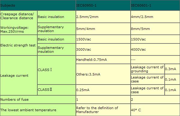
  • C3. What is different between information (EN60950-1) and medical (EN60601-1) safety standard?

    Answer:

    According to safety standard, the leakage current in EN60950-1 Class I cannot exceed 3.5mA; in EN60601-1 cannot exceed 0.3mA. Others criteria like safe distance and numbers of fuse are also different. Please consult the diagram below:

    faq02

  • C4. What is class 2, class II and LPS? What is the difference between class I and class II?

    Answer:

    Class I: Equipment where protection against electric shock is achieved by using basic insulation and also providing a means of connecting to the protective earth conductor in the building where by routing those conductive parts that are otherwise capable of assuming hazardous voltages to earth ground if the basic insulation fails. This means a class I SPS will provide a terminal/pin for earth ground connection.

    Class II: Equipment in which protection against electric shock does not rely on basic insulation only, but in which additional safety precautions, such as double insulation or reinforced insulation are provided, there being no reliance on either protective earth or installation conditions. This means a class II SPS does NOT have a terminal/pin for earth ground connection.

    LPS: When an electronic circuit is powered by a limit power source, its output current and power are under the limitation shown in Table 3.4, and the risk of fire can be reduced significantly. So, the safety distances and flammability rating of components can be much lower. In this way, the design cost for SPS compliant with LPS can be reduced as compared with non LPS SPS.

    C5. What is SELV? Are all MW SPSs compliant with SELV?

    Answer:

    This regulation applies to the secondary circuitry. The circuit should be designed to guarantee that under normal operating conditions, the voltage between any two touchable points should be less than 42.4Vpeak or 60Vdc. For class I equipment, it refers to “between any touchable point and the ground.” Under single fault conditions, the voltages between any two conductors of the SELV circuit and between any one such conductor and earth shall not exceed 42.4V peak or 60Vdc for a period longer than 0.2 seconds. Moreover, a limit of 71V peak or 120Vdc shall not be exceeded.

    According to requirements below, MW SPSs can comply with SELV.

    IEC 60950-1 (ITE SPS): voltage of o/p circuit is less than 60Vdc under normal condition.

    IEC 61347-2-13 (LED SPS): voltage of o/p circuit is less than 120Vdc under normal condition.


Others ↓