Mean Well Power Supply Stocking Warehouse
Power 277 LED Frequently Asked Questions
Below you’ll find a list of frequently asked questions regarding the LED product category. You can also browse our other sections regarding general and Magnetic FAQ’s through the buttons above. If you have any additional questions that are not listed in any of the FAQ section we have on our site, please feel free to contact us at: 877-878-2348
LED FAQ ↓
-
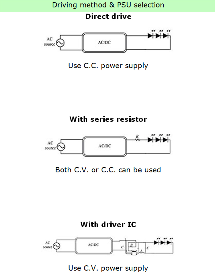
2. What are the most common LED driving methods?
Answer:
-
3. What are a few things to consider when selecting an LED power supply?
Answer:
A. Is the lighting system designed to work in direct drive mode?
- The combined LED forward voltage range (upper and lower) must fall within the LED power supply’s constant current voltage range. For example, if the LED Vf spec is 3.4 – 3.6V, when 6 are connected in a series the combined Vf will be 20.4 – 21.6V. In this case, a 24V unit must be selected with a constant current region of 18 – 24V.
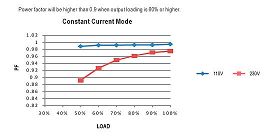
- For models with active PFC and the system PF requirement is > 0.9, load usage must be higher than what is specified on the PFC spec. The relationship between PF and output load can be found in the illustration below. The typical requirement is 75% load or above. Double check the spec for the model you are using to confirm the actual requirement.
- In areas with unstable AC voltage, such as heavy industrial zones or generator supply utilities, please select general usage LED series from the illustration below.
B. Lighting Systems designed to work with driver IC:
- The start up voltage of driver IC should be as close to the power supply rated voltage as possible.
- Driver IC needs stable voltage to function properly. It is highly recommended you use general usage series from the illustration below.
- For models with active PFC, and the system PF requirement is >0.9, load usage must be higher than as specified in the PFC spec. The relationship between PF and output load can be found in the illustration below. The typical requirement is 75% load or above. When using driver IC, possible system EMI issues could arise. After completing lighting system design, EMI must be double checked. For suggestions on system EMI problem solving, refer to question 11.
-
6. What are CV, CC, and CV + CC, which are often mentioned in LED power supply specifications?
Answer:
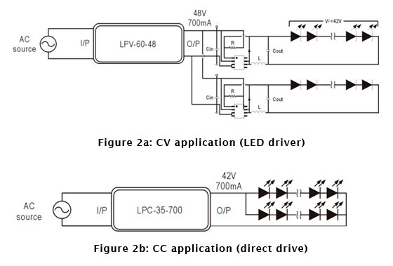
CV: Constant Voltage – Conventional power supplies will provide stable, regulated voltage (constant voltage) for load usage. Regardless of AC input variation (90 – 264 VAC) or load variation, output voltage will be regulated to within voltage tolerance specifications (single output unit typically 1 – 2%). For example, the LPV-60-48 used in powering LED driver + LED light strip, output voltage will remain constant at 48V, as shown in the illustration below.
CC: Constant Current – Designed to provide a stable output current (constant current), output voltage will be determined by LED total Vf. For example, using LED with Vf = 3.5V @ 350mA and with 12 pcs connected in a series, the toal Vf will be 3.5V x 12 = 42V. With 2 strips connected in parallel, the total If is 350mA x 2 = 700mA. If meanWell constant current LED power supply LPC-35-700 (Vin = 90 – 264VAC, Vout = 48V/700mA) is used to drive LED load directly, LED power supply will work in CC mode. Output voltage will drop to 42VDC while output current remains constant at 700 mA, as show in the illustration below.
CV + CC: A MeanWell Constant Current LED power supply possesses both “CV + CC’ characteristics. During startup it will operate in CV Mode, which is suitable for LED driver IC and series resistor applications. Once the output current requirement exceeds the rated current of the power supply and reaches the constant current region, the unit will remain in the CC Mode, which is suitable for direct drive of LEDs. CV + CC characteristics can be used in all types of LED setups, making system design more flexible.
-
7. Why is it that LED lamps designed with LED driver IC may sometimes cause a power supply startup failure? (Output voltage gets clamped by LEDs and cannot rise to rated level)
Answer:
Depending on circuit design, there could be several different operational problems. See below:
- Boost mode driver IC: The startup voltage of such driver IC is significantly lower than the total LED forward voltage. For this reason the IC will start up at a very low voltage level, usually about 1/2 of the power supply’s rated voltage, and, to meet the rated power requirement, the startup current will reach 2 time the power supply’s rated current. When the power supply is unable to provide this current, the LED CC driver will not activate.
- Buck mode driver IC: The selected power supply voltage is significantly higher than the LED forward voltage. For example, the power supply provides 48V but the LED lamp only needs 24V and the power ratings are equivalent. When power supply voltage reaches the LED conduction voltage the power supply will immediately go into Constant Current mode. At this moment the required power to start up the LED and driver is larger than what the power supply can provide, causing a malfunction of the driver circuit and the power supply to be clamped at LED forward voltage.
For boost mode design, we recommend raising the startup voltage of the driver IC to be as close to the power supply voltage as possible, or incorporate soft start function (see illustration below). Wait until the power supply voltage is established before starting the driver.
When selecting a power supply for buck mode, the output voltage of the power supply should be as close to the LED total voltage as possible, with excess power available (LED power/0.85).
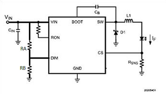
Example of driver IC soft start circuit:
DIM PIN is the startup pin for most PWM based drivers. It can also be designated as EN (Enable). DIM (or enable) is at 0v the internal connection to SW pin will be to set the Vstart for the
DRIVER IC:
Vstart = (VDIM/RB) x (RA + RB). The general rule is to set the Vstart at 5 – 10% higher than the total LED forward voltage. -
8. Why is it that, during LED power supply operation, the LED sometimes varies in brightness or flickers?
Answer:
Mean Well has developed many power supply series specifically for LED application. Single stage PFC was used in such developments due to low cost. This topology has the following restrictions:
- AC fluctuation – This topology does not use input bulk capacitor. For this reason, in areas with low AC quality, output voltage and current may become unstable, causing variation in LED brightness. If the input AC voltage is stable then this problem will not occur.
- Output ripple – This is also caused by lack of input bulk capacitor. As compared to power supplies using dual stage PFC, the ripple will be significantly larger (see illustration below). There could be instances where the low end of the ripple may be too low for the driver IC to operate properly and the LEDs will start to flicker. To solve this type of problem, the output voltage can be adjusted higher so the low end is higher than the driver’s minimum working voltage. You can also simply select a power supply unit with a higher rated voltage.
- Current Harmonics – Single stage PFC power supplies are optimized for constant current drive. Using these supplies as constant voltage sources, such as an application including cascading a constant current driver IC, the harmonics might worsen.
When operating in areas with unstable utility voltage, or with driver IC, we highly recommend using general application types found in the illustration on question 3 of this FAQ. Avoid using single stage PFC if possible, or contact Power 277.
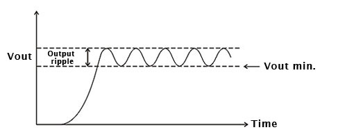
Output ripple for single stage PFC
-
9. Can LED power supplies be connected in parallel?
Answer:
Mean Well LED power supplies do not have parallel “current sharing” function, so they are not suitable for parallel connection. For high power requirements, please select higher wattage power supplies or divide the LED load into smaller sub-sections to be powered by individual power supplies. An example of such an LED configuration can be seen below. As shown in the illustration, the connection between -V of the LPC-35 units should be severed and not connected in common. On the contrary, small wattage LED loads can be connected in parallel and be powered by a single high wattage power supply. Make sure to take the ability to divide current evenly into consideration.
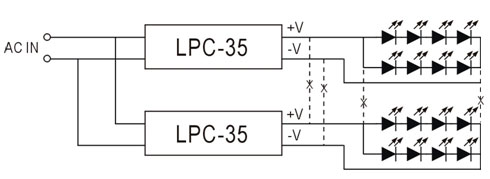
Setup for high wattage LED load supplied by two power supplies
-
11. Is it possible to run into EMI problems when using Mean Well LED power supplies? How do I go about solving such problems?
Answer:
Independent external type (metal/plastic enclosure):
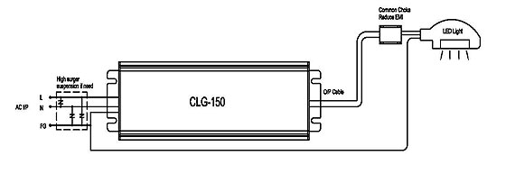
EMI test setup consists of isolated power supply and LED load. The EMI test report has data for both EN55015/EN55022. For Class I units with FG wire available, it is recommended to have both the power supply FG wire and lamp chassis connected to the Earth ground. This can reduce overall EMI noise. Depending on actual application, the input and output cables can be several meters long and this can lead to high common mode noise. If this is the case, we recommend adding common mode choke as close to the lamp head as possible. The same can also be done for AC input cable (refer to the diagram below).

Surge & EMI countermeasure
Buit-in PCB/U bracket:
For PLP/ULP Series, it’s design is based on being mounted on the same metal plane as the LED module. The EMI test setup is as shown below in the illustration. An iron plate is used to simulate a metal chassis. The output cable length will vary depending on system setup and this will have a big effect on the EMI. For this reason, we recommend twisting the output cable and adding a clamp on the core to reduce EMI noise.
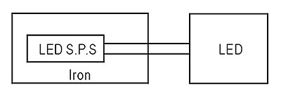
EMI setup for PCB & U type products
LED module with driver IC:
The previous EMI suggestions may not be as effective when it comes to designs with LED driver IC. EMI solutions will be more complicated due to the fact that the LED driver IC itself also switches at high frequency (few hundred kHz – MHz). For this reason, the driver IC must have an internal noise filter. Special attention should be paid to IC ground layout and placement of input and output capacitors and inductors. A general suggestion is show in the illustration below. Common mode choke and high frequency X capacitor must be incorporated in between the power supply and LED driver PCB.
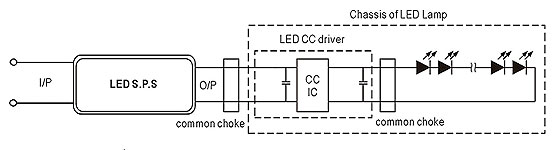
EMI solution for system with LED driver IC
-
12. What surge level can Mean Well LED power supplies withstand?
Answer:
Among Mean Well LED power supplies, the CLG and HLG models have the highest surge capability. They can withstand a heavy industry level of 4kV. If higher levels are required, external ZNR (470V) or gas tube (500V) can be added as shown in the illustration below. However, overall safety compliance must be taken into consideration. For applications with numerous lamp sets, a SPD (Surge Protection Device) can be in stalled to meet surge regulation requirements.
-
13. Do Mean Well LED power supplies allow adjustment of output voltage and current levels?
Answer:
Check the illustrations below. LED power supply comparison table to see which MEan Well LED power supply allows for V/I adjustments. A suitable unit can be picked based on the type of adjustment required. For the allowed adjustment range, please refer to the spec sheet. Tuning of the voltage and current levels can be done through the built-in VRs/potentiometers. PLN and ELN models require removal of the top cover in order to access the internal SVR1 and SVR2, see illustration A below for VR locations. For other series the VRs can be accessed through IoADJ and VoADJ openings, after the rubber stoppers have been removed. Once adjustments have been made, please make sure rate power is not exceeded and the rubber stoppers are properly reassembled.
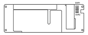
Fig A: VR locations for V/I adjustment
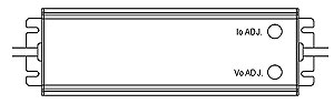
Figure B: V/I adjustment location
-
14. How do the dimming functions on the ELN-30/60-XXD(P) work?
Answer:
As shown in the illustrations below, an external signal can be applied to “DIM+” and “DIM-.” The signal can be either DC voltage (D Type) or PWM (P Type). By changing the signal levels as shown below, the output current limit can be controlled by the user. Please note that the relationship between the external signal and the output current level is non-linear. It can not be used for high precision dimming control.

View some of our PDF charts to find the right LED driver you need.